One negative thing about Sweden is that one is not allowed to have a TV receiver (of any kind, and especially not broken one) without paying a special fee of around €245 per year [This is no longer optional as of 2019 and is now a type of tax instead]. An alternative that enables playing couch co-op in the living room is to get a projector or large display that lacks a TV tuner/decoder.
We recently got such a display from Philips and found that the speakers are not quite powerful enough for a living room. So we connected it to a (somewhat retro) Philips AS9400/00 midisystem. The only problem was that the remote control has gone missing. So it was time to improvise.
With some spare parts just lying around it’s possible to build a remote control. If you already have an Arduino kit then almost everything needed is already there. The two parts that were missing from my kit were an NPN transistor and an infrared LED, but I luckily had a pair of these. The infrared LED is used to emit the signal from the remote control and the NPN transistor is used to drive the power to the LED.
Signals from infrared remotes are simply fast pulses of light and infrared LEDs are just like normal LEDs except they emit infrared light instead of visible light. The Arduino needs to turn the LED on and off in a certain pattern and at a certain speed for the receiver to be able to decode the signal. This can be done using the IRremote library. Some quick research showed that Philips devices mostly use the RC-5 protocol and that the Linux Infrared Remote Control Project has a file with all the RC-5 codes.
The digital pins on the Arduino are not powerful enough to drive the LED directly. Instead I used a BC547B model NPN transistor, but other NPN transistors should work fine as well. (It was the only NPN transistor I had). Be sure to read the data sheet for your transistor to ensure that it can handle the voltage and current needed, and also to check the pin configuration. They are different between models. The picture below made with Fritzing shows how I wired up the LED, transistor and two volume buttons:
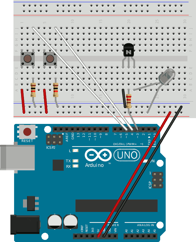
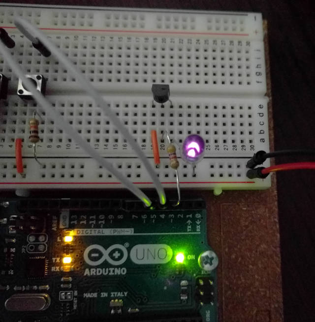
Other configurations are possible. I didn’t have a data sheet for the LED, so I need to guess the pin configuration. There are three markers on LEDs that you can use to see which pin is the anode and which is the cathode. Normally one edge of the LED is flat and this should be connected towards the ground. One leg is long and should be connected away from the ground. The large part inside the LED is connected towards ground. But with my infrared LED these markings did not match up with each other. The flat edge sits on the same side as the long leg. In my case the flat edge was correct, but other models can be marked differently. The best thing is to check with a camera:
This circuit needs some code. The constants for up and down were taken
from the LIRC project’s RC-5 table, after some experimentation to find
the right set of codes. The code length is 12 since 0x1000 is 1 <<
12.
IRsend irsend;
const int code_length = 12;
const unsigned long amp1_volume_up = 0x0000000000001410;
const unsigned long amp1_volume_down = 0x0000000000001411;
const int btn_up = 4;
const int btn_down = 5;
void setup()
{
Serial.begin(115200);
pinMode(LED_BUILTIN, OUTPUT);
pinMode(btn_up, INPUT);
pinMode(btn_down, INPUT);
}
void loop() {
unsigned long code = 0;
// Read the buttons
if (digitalRead(btn_up) == HIGH) {
code = amp1_volume_up;
} else if (digitalRead(btn_down) == HIGH) {
code = amp1_volume_down;
}
if (code == 0) {
delay(50);
return;
}
// Send the code.
for (int i = 0; i < 3; i++) {
digitalWrite(LED_BUILTIN, HIGH); // for visual feedback
irsend.sendRC5(code, code_length);
delay(50);
digitalWrite(LED_BUILTIN, LOW);
}
}
The remote control works but unfortunately the range is limited to just a few meters. The LED should be able to handle a much higher current, so that’s a point where some further experiments can be fruitful. Another idea is to use an ESP8266 instead of an Arduino and control the whole thing through WiFi.